 Bachelor Thesis · Mechanical Engineering
Energy Efficiency in Industrial Mills
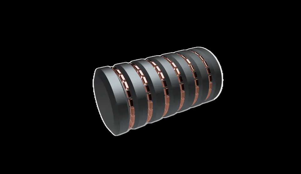
My bachelor thesis. Two grinding mills designed from scratch to cut the avoidable losses of a tumbling mill, one that is its own electric motor and a static one that moves its charge with electromagnetic fields, both modelled in 3D CAD and tested with FEM simulations.
In briefLink to this section
- Experimental studies show that in a ball mill less than 1% of the energy supplied actually breaks the material. The rest leaves as heat, vibration, noise and useless deformation.
- I separated the energy that fracture physically needs from the energy the machine wastes, then went after the two avoidable losses: the mechanical transmission and the rotation of the whole drum.
- Project I is a mill that is its own motor: a 2.6 m drum built as the rotor of an electric motor, with no gearbox. The electromagnetic simulation confirmed the direct-drive principle, but metre-scale permanent magnets make it impractical with today's materials.
- Project II is a motorless mill: a static 2 m × 4 m drum with 144 external coils that move a ferromagnetic charge. Magnetic flux does reach the channels where the charge sits, but the field is strongly non-uniform. Of the two, this is the more promising direction.
- Tools: 3D CAD, plus electromagnetic, thermal and static structural FEM in general-purpose multiphysics software. The results are qualitative, and I documented every simplification.
Why grinding millsLink to this section
Grinding (comminution, in the technical jargon) is one of the most energy-hungry operations in industry. Cement, ore, minerals, ceramics: almost everything solid goes through a mill at some point, and those mills draw huge amounts of power. When I was looking for a thesis topic, this seemed like a place where even a small improvement would add up.
Then I found the number the thesis is built on. Experimental studies show that in a ball mill less than 1% of the energy supplied actually goes into breaking the material. The other 99% leaves as heat, vibration, noise and useless deformation.
So I changed the question from "how do we grind better?" to "where exactly does the energy go, and which of those losses can a design legitimately remove?" To answer it, I first had to learn how to put numbers on the energy a mill needs.
The grinding lawsLink to this section
Over more than a century, engineers built empirical laws that link the energy spent to the size reduction achieved. I worked through them because I needed a yardstick to separate the energy physics demands from the energy the machine wastes. There are three classic laws, and a fourth that ties them together.
Rittinger (1867) assumes the energy is proportional to the new surface you create, so it suits very fine grinding:
Rittinger · fine grinding
Kick (1885) assumes instead that the energy depends on volume deformation and scales with the logarithm of the reduction ratio, which fits coarse crushing better:
Kick · coarse crushing
Bond (1951) sits between the two and became the industry standard. Plant designers still use it today:
Bond · the equation industry actually uses
wᵢ is the Bond Work Index: the kWh per tonne needed to grind a material from a (theoretically) infinite size down to 100 µm. d and D are the product and feed sizes. It is measured in the lab for each material and is still the main reference for sizing industrial grinding plants.
Charles unified all three in one differential form, where a single exponent n picks the regime:
Charles · the general model
n = 2 gives Rittinger, n = 1 gives Kick, n = 1.5 gives Bond.
What these laws describe is the irreducible energy of fracture, the ~1% that any mill has to spend. Everything above that comes from the machine, so I turned to the machine's losses.
Following the losses backwardLink to this section
I traced the power path backwards, from the rock to the wall socket. The charge is lifted and dropped inside a rotating drum; a shaft turns the drum; an electric motor drives the shaft through couplings and a gearbox. Every handover loses some energy.
Two operating parameters set the limits of the machine. First, the drum has to turn below its critical speed, the speed at which the charge centrifuges against the wall and grinding stops altogether:
Critical speed
Above the critical speed the grinding bodies stick to the shell and there is no impact. Real mills run at 50–90% of it, a compromise between throughput and stability.
Second, the power a tumbling mill draws climbs steeply with its geometry:
Draw power of a tumbling mill
D is the diameter, L the length, Δ the fill level, u the speed as a fraction of critical, ρc the charge density. The 2.5 power on D is why large mills are so power-hungry.
Along that chain, the avoidable losses sit in two places:
- the mechanical transmission: gears, couplings and bearings, each adding friction, heat and noise;
- rotating an entire massive steel drum just to stir a charge that fills barely half of it.
I gave each loss its own design, and I deliberately pushed both designs to the extreme.
Project I: the mill that is its own motorLink to this section
The first idea keeps the familiar tumbling mill but removes the drive train completely. Instead of a motor turning the drum through a gearbox, the drum becomes the rotor of the motor. There are two concentric cylinders: the outer one is fixed (the stator), and magnetic force spins the inner one, which is the mill shell itself. With no gears, couplings or belts, the only loss left is the motor's own efficiency.
CAD processLink to this section
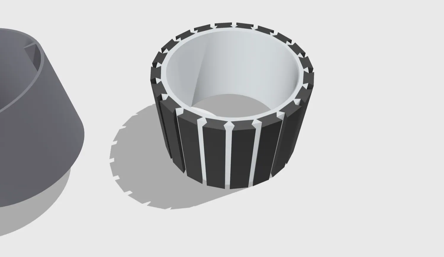
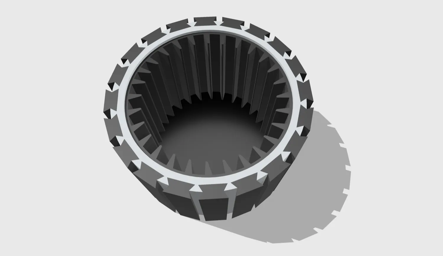
I started from a 3D model of a brushless motor and separated the rotor from the stator. I deleted the rotor's internal splined profile, which is useless here, and was left with a hollow cylinder that could hold the mill internals. Then I scaled the whole body ×10 to a realistic industrial size: 2.6 m in diameter.
Inside went a rubber liner carrying the lifters, the ribs that catch the charge on the way up and drop it onto the toe. I chose rubber because it is magnetically transparent, so it won't disturb the field, and because a rubber liner weighs up to 80% less than a steel one. Lower inertia means easier speed control and gentler transmitted loads. A 200 mm pitch around a 2.6 m diameter gave ~40 lifters, and I filleted every exposed edge so it would survive repeated impact.
Materials and electromagnetic modelLink to this section
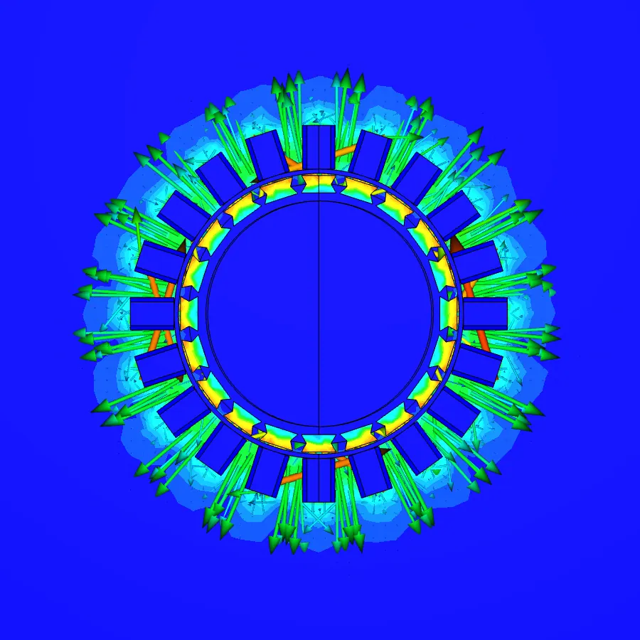
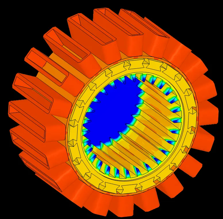
In the electromagnetic model every part got its real material: copper for the windings, M19 soft steel (with a defined B–H curve) for the permanent magnets, stainless steel for the frame, rubber for the liner, and a 7 × 7 m air domain around the machine so the field could develop without hitting the boundary. The coils use 1 mm wire, 6000 turns and 5 A. I checked carefully that the current direction stayed consistent from coil to coil, because a single reversed coil would generate an opposing field and fight the rotation.
The speed problemLink to this section
A standard brushless motor runs at 300–800 rad/s; dividing by the ×10 scale factor suggested ~30 rad/s. But the critical speed of a 2.6 m mill is only ωc = √(2 · 9.81 / 2.6) ≈ 2.75 rad/s. Keeping to 65% of that speed, the mill can turn at just ~1.8 rad/s (about 17 rpm). A standard brushless motor wants to spin two orders of magnitude faster than grinding allows, and even the scaled estimate of ~30 rad/s is roughly sixteen times the ~1.8 rad/s the mill can take. The large diameter a mill needs is exactly what pushes its critical speed so low.
ThermalLink to this section
I first tried a proper Conjugate Heat Transfer (CHT) model, treating the charge as a fluid filling half the drum with a rotating-wall boundary. The solver wouldn't accept it: a rotating-wall condition can only be applied to a solid–fluid interface, not to a fully solid surface. So I simplified. I fixed a temperature on the rubber wall at the instant the charge is in contact and read the gradients. The result is rough but useful: heat collects in the core of the lifters, because only their ends are cooled by the side walls. With the charge added to the model it draws some heat away, but the lifter cores remain the critical spot.
StructureLink to this section
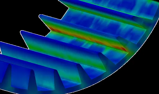
A static stress run on a single lifter, loaded at ~45° to match a realistic impact angle, showed stresses well within the rubber's limits. There was a sharp concentration, though, right at the square corner where the lifter meets the liner floor. The fix is the textbook one: a generous fillet there spreads the load and improves fatigue life.
So Project I works in principle: the electromagnetics confirmed that the stator and the rotating shell do generate the forces needed to move the charge. The simulations also showed that the system is very sensitive to dimensional tolerances and to how precisely the coil currents are controlled. Metre-scale permanent magnets are not realistically manufacturable, transportable or affordable, and today's magnetic materials don't scale linearly, because parasitic losses grow with size.
Project II: the motorless millLink to this section
Project I removed the transmission; Project II removes the rotation. Why spin a heavy steel drum at all, when the grinding charge is the only thing that needs to move? Here the drum stays still and electromagnetic fields stir only the charge.
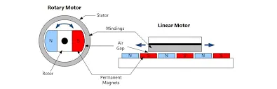
The plan was to make the grinding bodies ferromagnetic and steer them along controlled circular paths with a time-varying magnetic field. That would recreate the cascading and cataracting impacts of a real mill without a single rotating part. I took the idea from maglev and linear motors, which induce motion on the object itself instead of dragging the whole structure.
CADLink to this section
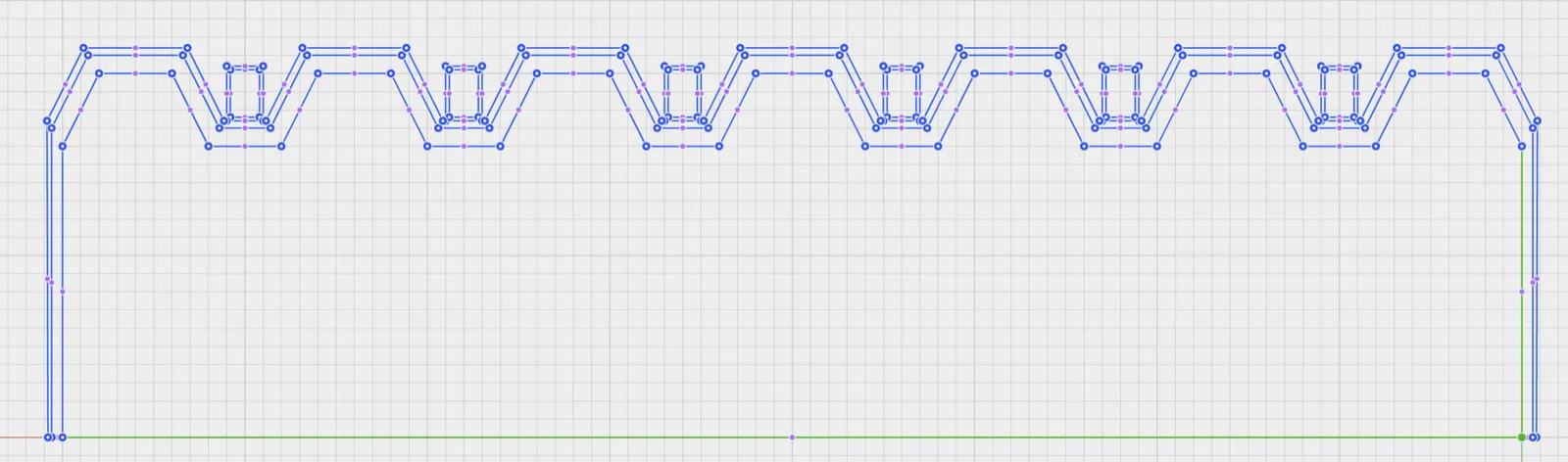
The drum is static, 2 m in diameter and 4 m long, with a 20 mm steel wall lined with 50 mm of vulcanised rubber. The inner surface is shaped into trapezoidal channels (200 mm each, with corners filleted at 40 mm so there are no weak sharp edges) that hold the charge where the field can act on it.
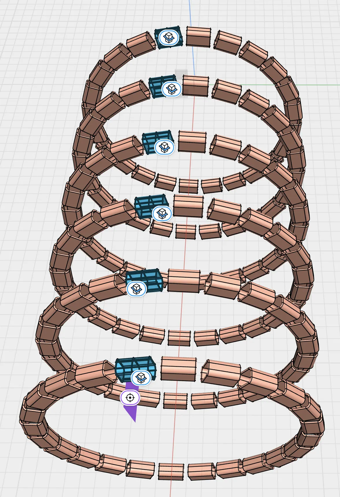
Around the outside sit 144 toroidal coils: 24 per ring at 15° spacing, in six rings along the axis. Each coil is driven independently with variable-frequency alternating current, so together they can build a rotating or pulsing field that walks the charge around the channels.
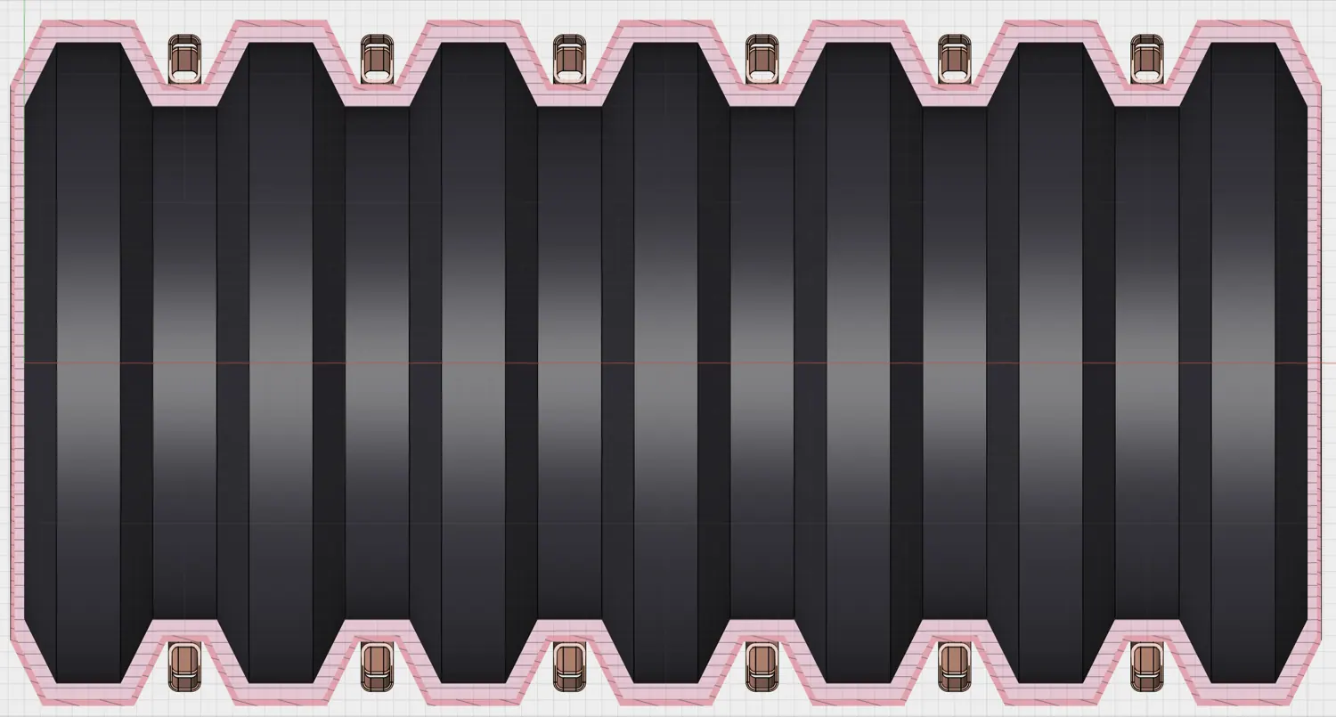
Electromagnetic simulationLink to this section
I set up two control volumes, air outside and the charge inside, and switched the field on. There is real magnetic flux inside the channels where the charge sits, so the coils can reach it and act on it. But the field is strongly non-uniform, with high-intensity hot spots next to near-dead zones, and it does not yet produce a net force with a clear thrust direction.
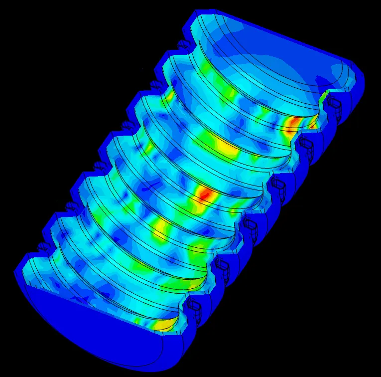
Thermal and structuralLink to this section
The thermal model showed heat concentrating in the central section (ambient air cools the ends, but not the middle). It also showed that the air gap between the coils and the frame helps dissipate heat, so closing it would only make things hotter. Structurally, the most loaded region is the floor of the central channels, where the charge slides and impacts; outside the channels the load is minimal.
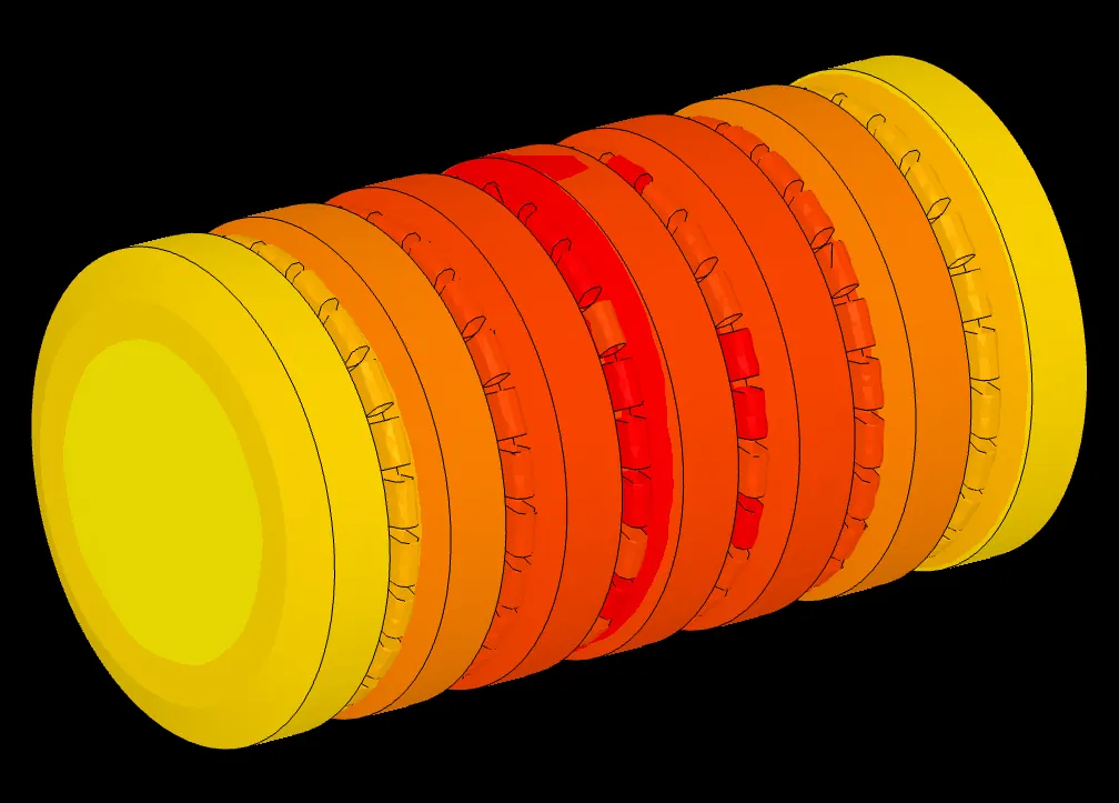
Overall, taking away the rotation removes the most energy-hungry and wear-prone element of a traditional mill. The simulations confirmed a measurable interaction between the coils and the charge. The non-uniform field and the complexity of 144 coils are real obstacles, but I see them as optimisation problems. One more possibility follows: if the material being ground is itself ferromagnetic, you could drive it directly and drop the grinding bodies altogether.
What the simulations could and couldn't sayLink to this section
I used general-purpose multiphysics software, because the specialised tools are proprietary and the industry leaders keep them in house. That forced compromises (the failed CHT run, the simplified thermal boundaries, the coil approximations), and I documented each of them in the thesis. These models are qualitative prototypes meant to find problems early. They can't certify a finished product.
The goal was to show that two ideas are physically coherent, and to map exactly what would have to be solved next.
ConclusionsLink to this section
Both mills could in theory bring meaningful efficiency gains, and both work in principle, but today's materials and costs hold them back. Project I is harder to build, mainly because of the metre-scale magnets. Project II gave less clean simulation results, but I think it is the more promising of the two. Each one removes a different one of the two big avoidable losses I traced at the start.
The economics look the same for both: high upfront cost and complexity, paid back over time by lower energy and maintenance bills, plus an environmental benefit from grinding cement, ore and minerals with less wasted power. I didn't build either machine. For a first piece of research, I think the useful result is showing that both are worth developing further.